Concrete erosion can quietly shorten the service life of hydraulic structures. Fast water carries sand, gravel, and suspended particles against exposed concrete surfaces. Over time, spillways, channels, culverts, and stilling basins may develop roughness, pitting, and surface loss.
This article presents ten practical tips to Improve the anti‑erosion performance of concrete in hydraulic projects. The guidance connects mixture design, construction quality, curing, drainage, and maintenance. It considers common site conditions, including turbulent flow, sediment impact, repeated wetting, and freezing temperatures. Engineers can evaluate aggregate hardness, water-to-cement ratio, air content, and surface finishing before construction begins. A dense concrete matrix helps resist water penetration and particle abrasion. Proper curing matters too.
Small details matter.
A well-finished surface may reduce weak zones around joints and edges. However, no single additive or coating solves every erosion problem. That assumption deserves careful review. Laboratory abrasion results may not fully represent field conditions, especially where flow changes suddenly or debris strikes the structure. Regular inspections can reveal early warning signs, such as exposed aggregate, hollow-sounding areas, or narrow cracks near waterlines. Repair decisions should follow project specifications, applicable standards, and advice from qualified professionals. The ten recommendations below offer a practical framework, but local testing remains essential. Each project has different water velocities, sediment loads, climate conditions, and construction limitations. Reliable performance comes from combining sound engineering with disciplined workmanship and realistic maintenance planning.
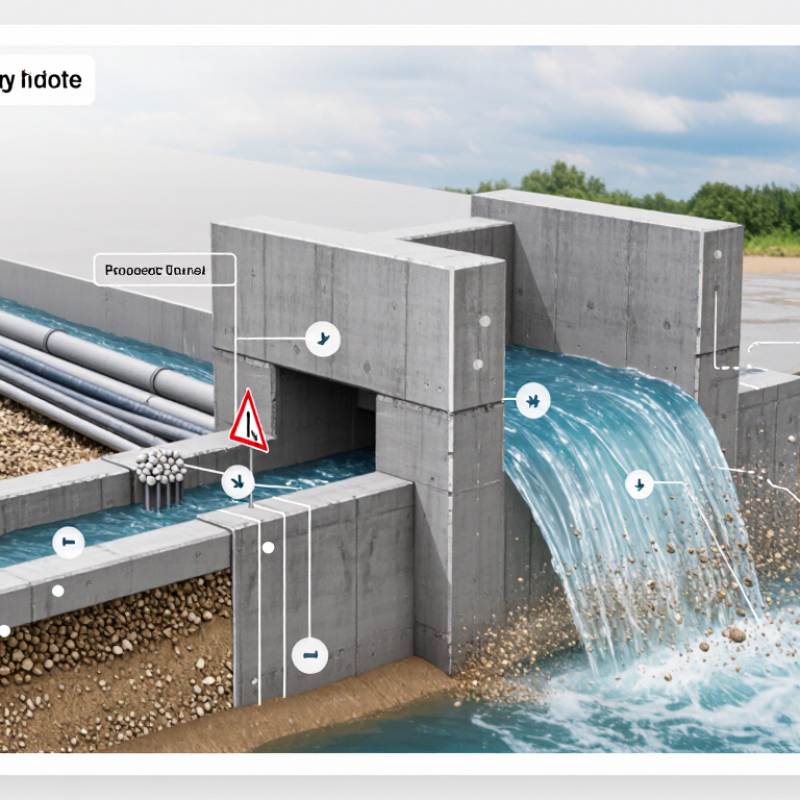
Hydraulic concrete erosion begins when moving water removes cement paste, exposes aggregate, and enlarges surface defects. Abrasive sediment acts like sandpaper, especially near spillways, outlets, and sharp channel bends. Cavitation adds vapor bubbles that collapse against the surface. The U.S. Army Corps of Engineers’ EM 1110-2-1601 identifies high velocity, pressure changes, and surface irregularities as key cavitation risks. Its guidance commonly treats velocities near 12 m/s as a serious design warning. The WMO State of Global Water Resources 2023 report found only about one-third of global river basins had normal conditions, increasing concern about extreme hydraulic loading.
Tip 1: Reduce the water-cement ratio. Tip 2: Use well-graded, hard aggregate. Tip 3: Consolidate concrete carefully around embedded parts. Tip 4: Finish surfaces without creating ridges. Tip 5: Detail smooth transitions at joints. A perfect mix does not exist. ACI 210R-03 emphasizes dense, durable concrete and careful hydraulic detailing for erosion-prone structures. Field experience shows that small honeycombs can become large cavities after repeated floods.
Tip 6: Limit sudden changes in flow direction. Tip 7: Protect vulnerable inlets with suitable lining systems. Tip 8: Check cavitation potential during design reviews. Tip 9: Inspect after every unusual flood. Tip 10: Map defects with photographs and measured depths. Repair timing matters. Delayed patching can leave exposed aggregate, allowing sediment to deepen the damage. Some inspections are still too visual; ultrasonic testing or core sampling may reveal deterioration beneath an apparently sound surface.
| No. | Improvement Tip | Main Erosion Cause Addressed | Recommended Practice | Useful Control Data | Verification Method |
|---|---|---|---|---|---|
| 1 | Use a low-permeability concrete mix | Water penetration, leaching, freeze–thaw damage, and surface weakening | Control the water-to-cementitious-materials ratio and use a well-graded aggregate system. A lower w/cm generally reduces capillary porosity when the concrete is properly cured. | Common durability-oriented designs often specify w/cm of approximately 0.40–0.50, subject to exposure, strength, permeability, and code requirements. | Slump and w/cm control, compressive-strength testing, rapid chloride permeability or bulk-resistivity testing, and water-absorption testing |
| 2 | Specify adequate compressive and tensile strength | Aggregate impact, abrasive sediment, cavitation-related damage, and cracking | Select strength based on hydraulic loading, abrasion exposure, structural demand, and the quality of construction—not strength alone. Dense, well-cured concrete normally performs better than weak or porous concrete. | Hydraulic structures frequently use design strengths in the approximate range of 30–50 MPa, but the required value must be established by project design and exposure assessment. | Standard compressive-strength tests, splitting-tensile tests, petrographic examination, and surface-abrasion testing where required |
| 3 | Use supplementary cementitious materials appropriately | Permeability, chemical attack, alkali–silica reaction, and paste abrasion | Evaluate fly ash, slag cement, or silica fume through trial mixtures. These materials can refine pore structure and reduce permeability, although early-age strength and curing requirements may change. | Typical trial-mixture replacement levels may range from about 15–40% for fly ash or slag and approximately 5–10% for silica fume, depending on material properties and specification limits. | Strength development, setting time, permeability, drying shrinkage, and resistance to the project-specific chemical environment |
| 4 | Choose hard, durable aggregates | Suspended-sediment abrasion, impact from transported gravel, and aggregate loss | Use clean, well-bonded, abrasion-resistant aggregate with suitable particle size, shape, and soundness. Avoid weak, friable, porous, or highly weathered particles. | Aggregate selection should satisfy the applicable abrasion, soundness, absorption, and petrographic requirements; limits vary by governing standard and exposure. | Los Angeles abrasion or Micro-Deval testing, soundness testing, water absorption, and petrographic analysis |
| 5 | Provide proper air entrainment where freeze–thaw exposure exists | Hydraulic pressure from freezing water, scaling, and repeated freeze–thaw cycles | Use a stable, properly distributed entrained-air system for concrete exposed to freezing and thawing while saturated. Air content should be selected according to aggregate size and exposure conditions. | For many freeze–thaw applications, total air content is commonly specified around 4–8%; the required value depends on nominal maximum aggregate size and the governing specification. | Fresh-air testing, air-void spacing and specific-surface analysis, freeze–thaw durability testing, and surface-scaling inspection |
| 6 | Apply sufficient curing and protect the surface | Early drying, plastic shrinkage, weak surface paste, and premature abrasion | Begin curing as soon as practical and maintain moisture and temperature conditions that support hydration. Prevent rapid evaporation, traffic, impact, and flowing water during early strength gain. | A commonly used minimum moist-curing period is 7 days for many ordinary concrete mixtures; project specifications may require longer periods, especially with supplementary cementitious materials. | Curing records, temperature and evaporation monitoring, surface pull-off tests, maturity data, and visual inspection for plastic-shrinkage cracking |
| 7 | Improve hydraulic geometry and surface finish | Turbulence, flow separation, vortices, and cavitation | Eliminate abrupt offsets, honeycombing, poorly aligned joints, and rough projections. Use smooth transitions, correctly formed inverts, and properly detailed changes in slope or direction. | Cavitation risk depends on local pressure, velocity, surface irregularity, and geometry; there is no single safe velocity applicable to every hydraulic structure. | As-built survey, laser or profile measurements, hydraulic modeling, flow observation, and inspection of pitting near transitions |
| 8 | Use fibers and crack-control reinforcement when appropriate | Cracking, local spalling, impact damage, and loss of surface material | Control restraint and thermal cracking through reinforcement, joint detailing, mixture design, and temperature management. Fibers may improve crack distribution and toughness but do not replace structural reinforcement unless specifically designed for that purpose. | Fiber dosage and reinforcement spacing must be determined by structural and durability design; crack-width limits are project-specific. | Crack mapping, crack-width measurement, flexural toughness testing, cover inspection, and structural review |
| 9 | Install compatible protective overlays or repairs | Severe abrasion, cavitation, chemical exposure, and localized deterioration | Consider dense repair mortar, polymer-modified concrete, silica-fume concrete, or other engineered overlays only after correcting the underlying hydraulic and structural cause. | The overlay must be compatible in bond, shrinkage, stiffness, permeability, thermal movement, and resistance to the expected hydraulic loading. | Surface preparation inspection, pull-off bond testing, thickness checks, permeability testing, and post-repair abrasion inspection |
| 10 | Control sediment, debris, and maintenance conditions | Long-term abrasion, impact, blockage, and concentrated high-velocity flow | Manage upstream sediment and debris where feasible, maintain screens and gates, remove deposits, and repair defects before they enlarge under hydraulic action. | Inspection frequency should reflect sediment load, flow velocity, seasonal conditions, freeze–thaw exposure, and the consequence of failure. | Routine visual inspections, underwater surveys, photographic records, profile measurements, and erosion-depth trend analysis |
Moving water removes cement paste and exposes aggregate. Suspended sediment then wears the surface like sandpaper.
Spillways, outlets, inlets, and sharp channel bends face higher risks. Flow direction changes can intensify local damage.
Pressure changes create vapor bubbles in fast water. When bubbles collapse, they strike irregular surfaces and enlarge small defects.
No. Velocity, pressure changes, and surface irregularities work together. Around 12 meters per second deserves serious design review.
Use a low water-cement ratio with enough workability for complete placement. Select clean, hard, well-graded aggregate.
Poor compaction leaves hidden channels and honeycombs. Repeated floods can turn a small void into a deep cavity.
No. Strength alone can mislead. Weak curing, poor air-void distribution, or surface ridges may still invite erosion.
Cure continuously after finishing. Protect surfaces from rapid drying, temperature changes, and early water flow.
Inspect after every unusual flood. Photograph defects, measure depths, and examine suspicious areas with ultrasonic testing or core sampling.
Repair exposed aggregate promptly. Delayed patching lets sediment deepen the damage. Still, visual inspection alone may miss internal deterioration.
Hydraulic concrete structures are constantly exposed to flowing water, suspended particles, pressure changes, and repeated wetting and drying, all of which can gradually damage their surfaces. To Improve the anti‑erosion performance of concrete in hydraulic projects, engineers should first understand the causes and severity of hydraulic wear. Selecting hard, durable, well-graded aggregates can reduce particle loss, while a carefully designed mix with a low water-to-cement ratio, adequate strength, low permeability, and proper compaction helps create a dense and durable concrete matrix.
Protection should also continue after placement. Suitable surface treatments, smooth finishes, sound construction joints, and effective curing can limit water penetration and surface deterioration. Regular inspections are essential for identifying abrasion, cracking, exposed aggregate, and other early signs of damage. Prompt repairs using compatible materials, combined with routine cleaning, drainage control, and monitoring of flow conditions, can prevent minor defects from developing into major structural problems. A coordinated approach involving material selection, construction quality, protective measures, and long-term maintenance offers the most reliable erosion resistance.

 Shengchuang Building